Technical details
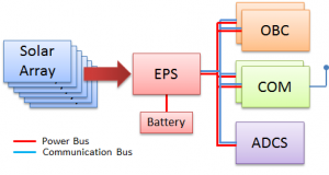
Simplified block diagram of the satellite
We divide the satellite in 4 electrical subsystems and the structure:
- On-Board Computer (OBC)
- Attitude Determination and Control System (ADCS)
- Electrical Power System (EPS)
- Communication System (COM)
- Structure (STRU)
On-Board Computer
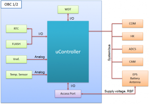
The OBC controls the operational processes of the satellite. In view of its mission critical nature, it was also designed for reliability. OBC consists of two identical units operating as a cold redundant system. OBC1 and OBC2 are exactly identical, running the same software and connecting the same way to the other units of the satellite. The two OBCs cannot communicate with each other. The power supply unit ensures that only one of them is turned on at any time. OBCs can identify themselves and the telemetry data show which OBC is currently working.
The OBC is implemented as a four layer circuit board. The board also includes the circuitry required to combine the two OBCs and the control signals. Furthermore, the board has an Access Port connector through which the battery can be charged and wired communication with the computer can be maintained. Following the assembly of the satellite, this is the only connector which remains accessible.
Attitude Control and Determination System
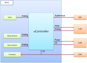
The ADCS panel is located between the satellite’s onboard central computer and the radio communication unit. The panel includes the ADCS sensors and the microcontroller which collects the data and communicates with the central computer’s microcontroller using the I2C protocol. The actuating signal calculated by the microcontroller drives the power amplifier stage, also included on the panel, controlling the coils. This stage is a full bridge composed of field effect transistors, and the coil is located across the bridge. The coil’s average current is controlled by the actuating signal which has a constant frequency but is modulated in its duty cycle. ADCS sends its data to the radio communication unit via the central computer. This makes it possible to send telemetric data about the operation of ADCS to ground stations, and to adjust the operating modes and parameters of the controller.
Masat-1’s ADCS has a rich selection of instruments, including a digital compass equipped with a three-axis magnetic induction field strength meter and a three-axis accelerometer. The selection also includes a three-axis microelectronic-mechanic angular velocity meter. Furthermore, the analog signals supplied by the photodiodes located on each side are processed by a separate microcontroller integrated on the ADCS panel.
Communication System
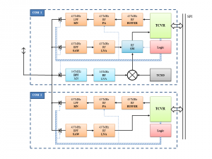
There is no individual intelligence in the COM, all of the necessary internal control functions are performed on gate-level. The RF transmit power of the COM is 100mW in low-power mode and it is 400mW in high-power mode. In default configuration every 4th TM transmission is in high-power mode.
As the used single chip transceiver has an operating frequency range within the 200-900 MHz band. The transceiver was designed with short and medium range applications in mind; therefore the maximum TX power is below 16 dBm. This is not sufficient to cover the required range, so the addition of an RF PA became inevitable. To prevent excessive power consumption, only the required units are turned on at a time. This switching is performed within the COM unit using a logic-gate based state-machine. Further design complications originate from the need of redundancy. Each unit on the block diagram is duplicated, and the switchover mechanism has to be well-planned to work properly in case of any possible failure. The change between the redundant components is driven by the OBC.
The realized modulation schemes are OOK and 2-GFSK. On the downlink side there are three possible operating modes using two different modulation schemes. The first mode uses On-Off Keying (OOK). As Masat-1 will operate in the radio amateur frequency band, the transmission of its callsign (HA5MASAT) is necessary at the beginning of each transmission sequence. For that purpose, OOK modulation is used with Morse code.
Electrical Power System
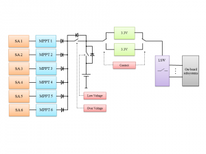
The electrical power system is designed to manage the primary and secondary power sources of the satellite and to distribute their energy among the onboard subsystems. Since this system is mission critical, reliability was a key aspect during its design. Similarly to the satellite’s other subsystems, the electrical power system is also redundant, to protect it from a single point of failure. Masat-1’s primary energy sources are the solar panels located on the six sides of the cube, generating electricity for the satellite’s operation when illuminated by the Sun. The solar panels feed their energy to the uncontrolled power bus through six independent matching circuits. The current supplied by the solar panels are summed via series insulating diodes which prevent the current from flowing back into dark or defective panels. When the satellite passes through an Earth shadow in its orbit, the required power is supplied by a single cell Li-ion battery, used as a secondary power source. This battery is directly connected to the onboard power bus, whose uncontrolled voltage is thus determined by the charge status of the battery. The power bus is filtered by capacitors to prevent sudden load changes from generating extreme voltage swings and propagating disturbances.
The controlled 3.3 V voltage required by the onboard subsystems are produced by two voltage reducing converters working in a cold backup redundant scheme. Onboard energy is distributed at the stabilized 3.3 V level through LSW current limiter switches. The energy distribution is controlled by the on-board computer.
Structure
The structure holds the components in place and also protects them from external effects. Structural elements can be categorized into two main categories:
- primary structural elements
- secondary structural elements
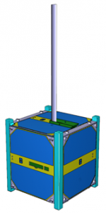
The primary structural elements form the skeleton of the satellite, ensuring the mechanical stability of the structure; while the secondary structural elements give appropriate mechanical support for specific electric parts and panels. The material of the structure is aerospace aluminium, which is made suitable by high-quality machining. The structure must tolerate the extreme acceleration and vibration stress of the launch, and it must also provide appropriate protection from the harsh effects of space environment (e.g. radiation, extreme temperature stress, etc.).
University
Cooperation
Sponsors
- AduPrint
- Altium
- Anico Kft.
- Azurspace
- BL-Electronics
- Bonn Hungary
- Carinex
- ChipCAD
- COOPTIM Ipari Kft
- Dension
- DND Telecom Center Kft.
- DSI Informationstechnik
- Dunaújvárosi Főiskola
- EADS Astrium GmbH
- ELMŰ
- Europrint
- Evosoft
- Exasol Kft.
- Faludi Wolf Theiss
- Farmelco Kft.
- GD Gép és Daru Kft.
- HFT Kft.
- HP Magyarország
- Hungaro DigiTel Kft.
- Infoterra Hungary Kft
- KFKI RMKI
- LHT Budapest
- LOMEX
- Magnetec-Ungarn
- Magyar Villamos Művek
- Magyarok a Marson
- Microchip
- National Instruments
- Nikon
- NMHH
- NuSil
- Paksi Atomerőmű
- Puskás Technikum
- Rádióvilág
- Ricoh Hungary Kft.
- RSOE
- Sagax Kft.
- SGF Kft.
- Siemens
- Silicon Labs
- Sphere Consulting Kft.
- Totaltel
- Űrvilág Hírportál
- Wacker Chemie
Design tools
Calendar
| M | T | W | T | F | S | S |
|---|---|---|---|---|---|---|
| 1 | 2 | 3 | 4 | 5 | 6 | |
| 7 | 8 | 9 | 10 | 11 | 12 | 13 |
| 14 | 15 | 16 | 17 | 18 | 19 | 20 |
| 21 | 22 | 23 | 24 | 25 | 26 | 27 |
| 28 | 29 | 30 | 31 | |||


